
この記事でわかる事
・VRF-liteの仕組みがわかります(vrfルーティングテーブル等々)
・VRF-lite設定が分かり、実務に反映できます。
・CCNP試験のサポートになります。
VRFはどこに設定する?
VRFはInterfaceに設定します。以下の設定例と記載します。
【物理IFの場合】
interface GigabitEthernet0/1
ip vrf forwarding TEST-VRF
ip address 10.1.1.100 255.255.255.0
【VLAN IFの場合】
interface Vlan10
ip vrf forwarding TEST-VRF
ip address 10.1.1.100 255.255.255.0
【Sub IFの場合】
interface GigabitEthernet0/0.100
encapsulation dot1Q 100
ip vrf forwarding TEST-VRF
ip address 10.1.1.100 255.255.255.0
設定したVRFを確認
R3#show ip vrf
Name Default RD Interfaces
A1 1:1 Gi0/0.100
Gi0/1
B1 2:2 Gi0/0.200
Gi0/2
R3#show ip vrf interfaces
Interface IP-Address VRF Protocol
Gi0/0.100 10.34.1.3 A1 up
Gi0/1 10.13.1.3 A1 up
Gi0/0.200 10.34.1.3 B1 up
Gi0/2 10.23.1.3 B1 up
R3#show ip vrf detail
VRF A1 (VRF Id = 3); default RD 1:1; default VPNID <not set>
Old CLI format, supports IPv4 only
Flags: 0xC
Interfaces:
Gi0/0.100 Gi0/1
Address family ipv4 unicast (Table ID = 0x3):
Flags: 0x0
No Export VPN route-target communities
No Import VPN route-target communities
No import route-map
No global export route-map
No export route-map
VRF label distribution protocol: not configured
VRF label allocation mode: per-prefix
VRF B1 (VRF Id = 4); default RD 2:2; default VPNID <not set>
Old CLI format, supports IPv4 only
Flags: 0xC
Interfaces:
Gi0/0.200 Gi0/2
Address family ipv4 unicast (Table ID = 0x4):
Flags: 0x0
No Export VPN route-target communities
No Import VPN route-target communities
No import route-map
No global export route-map
No export route-map
VRF label distribution protocol: not configured
VRF label allocation mode: per-prefix
R3#
VRFを設定するメリット
VRFを設定する事により、基本同一のVRF内での通信は可能で、別VRFとは通信できなくなります。
(別VRF間で通信しなくてはならない場合は、VRF-Leakにより解決します)
例) 【VRF1】と【VRF2】の2つのVRFがあった場合
VRF1に所属するデバイス間の通信可能です。
VRF1に所属するデバイスとVRF2に所属するデバイスと基本通信できません。
VRFで分かれる仕組み
ルータやスイッチ内でVRF1とVRF2を仮想的に分離しているためです。
分離することにより、ルーティングテーブルもそれぞれ分離します。
例) VRF1とVRF2の2つのVRFがあった場合、ルーティングテーブルはえ3つ作成されます。
- グローバルルーティングテーブル (元々存在しているテーブルで、VRF1にもVRF2にも属さない)
- VRF1用のルーティングテーブル(新規に作成されたテーブルで、VRF1のルーティングを表す)
- VRF2用のルーティングテーブル(新規に作成されたテーブルで、VRF2のルーティングを表す)
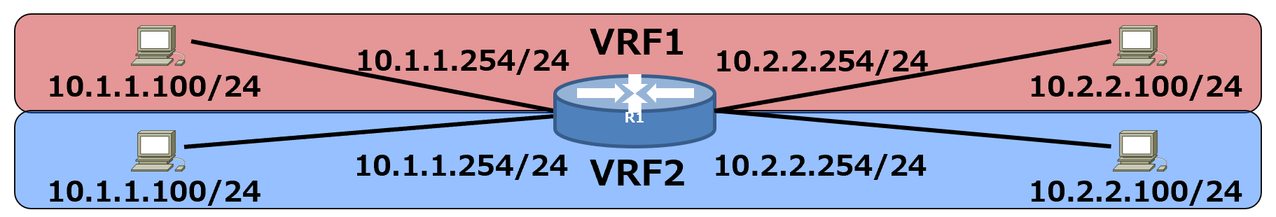
また、ルーティングテーブルがそれぞれ分離されることにより、VRF間で同一のセグメント/IPアドレスを設定しても問題ありません。
例)以下の構成のように、VRF1とVRF2で全く同じにしても問題ありません。
(VRFを使わないNWの場合、通信ができないどころか、ルータには設定すら入りません)
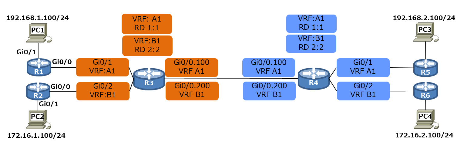
検証NW構成
検証NW仕様
・R3とR4に2つのVRFを設定しました。(設定したVRF:A1とB1)
・今回はルータに設定しているので、物理IFとSub-IFにVRFを設定しています。
・A1に属するPC1(A1所属)⇔PC3(A1所属)は通信可能です。
・A2に属するPC2(B1所属)⇔PC4(B1所属)は通信可能です。
・通信できないのでは、以下のデバイスです。
PC1(A1所属)⇔PC2(B1所属)
PC1(A1所属)⇔PC4(B1所属)
PC2(B1所属)⇔PC3(A1所属)
・ルーティングはOSPFを利用しました(その他ダイナミックルーティング、staticでも可)
各ルータのルーティングテーブル
R3-show ip route
R3#show ip route vrf A1 ospf
Gateway of last resort is not set
O 10.45.1.0/24 [110/2] via 10.34.1.4, 00:17:03, GigabitEthernet0/0.100
O 192.168.1.0/24 [110/2] via 10.13.1.1, 00:06:35, GigabitEthernet0/1
O 192.168.2.0/24 [110/3] via 10.34.1.4, 00:05:36, GigabitEthernet0/0.100
R3#show ip route vrf B1 ospf
Gateway of last resort is not set
O 10.46.1.0/24 [110/2] via 10.34.1.4, 00:17:11, GigabitEthernet0/0.200
O 172.16.1.0 [110/2] via 10.23.1.2, 00:04:18, GigabitEthernet0/2
O 172.16.2.0 [110/3] via 10.34.1.4, 00:05:08, GigabitEthernet0/0.200
R3#show ip route
Gateway of last resort is not set
R3#
R4-show ip route
R4#show ip route vrf A1 ospf
Gateway of last resort is not set
O 10.13.1.0/24 [110/2] via 10.34.1.3, 00:26:07, GigabitEthernet0/0.100
O 192.168.1.0/24 [110/3] via 10.34.1.3, 00:15:38, GigabitEthernet0/0.100
O 192.168.2.0/24 [110/2] via 10.45.1.5, 00:14:39, GigabitEthernet0/1
R4#show ip route vrf B1 ospf
Gateway of last resort is not set
O 10.23.1.0/24 [110/2] via 10.34.1.3, 00:26:13, GigabitEthernet0/0.200
O 172.16.1.0 [110/3] via 10.34.1.3, 00:13:18, GigabitEthernet0/0.200
O 172.16.2.0 [110/2] via 10.46.1.6, 00:14:09, GigabitEthernet0/2
R4#show ip route ospf
Gateway of last resort is not set
R4#
R1-show ip route
R1#show ip route ospf
Gateway of last resort is not set
O 10.34.1.0/24 [110/2] via 10.13.1.3, 00:30:48, GigabitEthernet0/0
O 10.45.1.0/24 [110/3] via 10.13.1.3, 00:30:17, GigabitEthernet0/0
O 192.168.2.0/24 [110/4] via 10.13.1.3, 00:18:49, GigabitEthernet0/0
R1#
R2-show ip route
R2#show ip route ospf
Gateway of last resort is not set
O 10.34.1.0/24 [110/2] via 10.23.1.3, 00:31:14, GigabitEthernet0/0
O 10.46.1.0/24 [110/3] via 10.23.1.3, 00:30:52, GigabitEthernet0/0
O 172.16.2.0/24 [110/4] via 10.23.1.3, 00:18:49, GigabitEthernet0/0
R2#
R5-show ip route
R5#show ip route ospf
Gateway of last resort is not set
O 10.13.1.0/24 [110/3] via 10.45.1.4, 00:31:37, GigabitEthernet0/0
O 10.34.1.0/24 [110/2] via 10.45.1.4, 00:31:37, GigabitEthernet0/0
O 192.168.1.0/24 [110/4] via 10.45.1.4, 00:21:08, GigabitEthernet0/0
R5#
R6-show ip route
R6#show ip route ospf
Gateway of last resort is not set
O 10.23.1.0/24 [110/3] via 10.46.1.4, 00:32:18, GigabitEthernet0/0
O 10.34.1.0/24 [110/2] via 10.46.1.4, 00:32:18, GigabitEthernet0/0
O 172.16.1.0/24 [110/4] via 10.46.1.4, 00:19:28, GigabitEthernet0/0
R6#
各ルータコンフィグ
R1-config
hostname R1
!
interface GigabitEthernet0/0
ip address 10.13.1.1 255.255.255.0
duplex auto
speed auto
media-type rj45
!
interface GigabitEthernet0/1
ip address 192.168.1.254 255.255.255.0
duplex auto
speed auto
media-type rj45
!
router ospf 1
passive-interface GigabitEthernet0/1
network 10.13.1.0 0.0.0.255 area 0
network 192.168.1.0 0.0.0.255 area 0
!
R1#
R2-config
hostname R2
!
interface GigabitEthernet0/0
ip address 10.23.1.2 255.255.255.0
duplex auto
speed auto
media-type rj45
!
interface GigabitEthernet0/1
ip address 172.16.1.254 255.255.255.0
duplex auto
speed auto
media-type rj45
!
router ospf 1
passive-interface GigabitEthernet0/1
network 10.23.1.0 0.0.0.255 area 0
network 172.16.1.0 0.0.0.255 area 0
!
R2#
R3-config
hostname R3
!
ip vrf A1
rd 1:1
!
ip vrf B1
rd 2:2
!
interface GigabitEthernet0/0
no ip address
duplex auto
speed auto
!
interface GigabitEthernet0/0.100
encapsulation dot1Q 100
ip vrf forwarding A1
ip address 10.34.1.3 255.255.255.0
!
interface GigabitEthernet0/0.200
encapsulation dot1Q 200
ip vrf forwarding B1
ip address 10.34.1.3 255.255.255.0
!
interface GigabitEthernet0/1
ip vrf forwarding A1
ip address 10.13.1.3 255.255.255.0
duplex auto
speed auto
media-type rj45
!
interface GigabitEthernet0/2
ip vrf forwarding B1
ip address 10.23.1.3 255.255.255.0
duplex auto
speed auto
media-type rj45
!
router ospf 100 vrf A1
network 10.13.1.0 0.0.0.255 area 0
network 10.34.1.0 0.0.0.255 area 0
!
router ospf 200 vrf B1
network 10.23.1.0 0.0.0.255 area 0
network 10.34.1.0 0.0.0.255 area 0
!
R3#
R4-config
hostname R4
!
ip vrf A1
rd 1:1
!
ip vrf B1
rd 2:2
!
interface GigabitEthernet0/0
no ip address
duplex auto
speed auto
media-type rj45
!
interface GigabitEthernet0/0.100
encapsulation dot1Q 100
ip vrf forwarding A1
ip address 10.34.1.4 255.255.255.0
!
interface GigabitEthernet0/0.200
encapsulation dot1Q 200
ip vrf forwarding B1
ip address 10.34.1.4 255.255.255.0
!
interface GigabitEthernet0/1
ip vrf forwarding A1
ip address 10.45.1.4 255.255.255.0
duplex auto
speed auto
media-type rj45
!
interface GigabitEthernet0/2
ip vrf forwarding B1
ip address 10.46.1.4 255.255.255.0
duplex auto
speed auto
media-type rj45
!
router ospf 100 vrf A1
network 10.34.1.0 0.0.0.255 area 0
network 10.45.1.0 0.0.0.255 area 0
!
router ospf 200 vrf B1
network 10.34.1.0 0.0.0.255 area 0
network 10.46.1.0 0.0.0.255 area 0
!
R4#
R5-config
hostname R5
!
interface GigabitEthernet0/0
ip address 10.45.1.5 255.255.255.0
duplex auto
speed auto
media-type rj45
!
interface GigabitEthernet0/1
ip address 192.168.2.254 255.255.255.0
duplex auto
speed auto
media-type rj45
!
router ospf 1
passive-interface GigabitEthernet0/1
network 10.45.1.0 0.0.0.255 area 0
network 192.168.2.0 0.0.0.255 area 0
!
R5#
R6-config
hostname R6
!
interface GigabitEthernet0/0
ip address 10.46.1.6 255.255.255.0
duplex auto
speed auto
media-type rj45
!
interface GigabitEthernet0/1
ip address 172.16.2.254 255.255.255.0
duplex auto
speed auto
media-type rj45
!
router ospf 1
passive-interface GigabitEthernet0/1
network 10.46.1.0 0.0.0.255 area 0
network 172.16.2.0 0.0.0.255 area 0
!
R6#
まとめ
●Configとルーティングテーブルより、デバイス間では以下の通信のみが可能です。
⇒A1に属するPC1(A1所属)⇔PC3(A1所属)は通信可能です。
⇒A2に属するPC2(B1所属)⇔PC4(B1所属)は通信可能です。
●デバイス間で通信不可になるのは以下です。
⇒PC1(A1所属)⇔PC2(B1所属)
⇒PC1(A1所属)⇔PC4(B1所属)
⇒PC2(B1所属)⇔PC3(A1所属)
●ルーティングテーブルがVRF毎に作成され、そのVRFでのみ有効な宛先がテーブルに載ります。
●VRF毎にOSPFを設定する場合は、router ospf 【process番号】 vrf 【VRF名】