
【概要】
PBRのオプションである[ip next-hop recursive] について説明します。[ip next-hop recursive]はPBRで[set ip next-hop]で設定したNext-hopに障害あった場合の代替えnext-hopとして設定します。
【例えば】
route-map ●●● permit 10
match ip address △△△
set ip next-hop x.x.x.x
set ip next-hop verify-availability
set ip next-hop recursive y.y.y.y ・・・①
next-hopは以下のようになります。
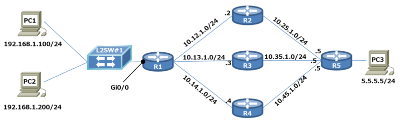
NW構成 (Cisco Modeling Lab利用)
Config
R1-config
hostname R1
!
interface GigabitEthernet0/0
ip address 192.168.1.254 255.255.255.0
ip policy route-map R-MAP
!
interface GigabitEthernet0/1
ip address 10.12.1.1 255.255.255.0
ip ospf cost 10
!
interface GigabitEthernet0/2
ip address 10.13.1.1 255.255.255.0
ip ospf cost 20
!
interface GigabitEthernet0/3
ip address 10.14.1.1 255.255.255.0
ip ospf cost 30
!
router ospf 1
passive-interface GigabitEthernet0/0
network 0.0.0.0 255.255.255.255 area 0
!
ip access-list extended PBR
permit ip host 192.168.1.100 host 5.5.5.5
!
route-map R-MAP permit 10
match ip address PBR
set ip next-hop 10.13.1.3
set ip next-hop verify-availability
set ip next-hop recursive 10.14.1.4
!
control-plane
!
end
R2-config
hostname R2
!
interface GigabitEthernet0/0
ip address 10.12.1.2 255.255.255.0
ip ospf cost 10
!
interface GigabitEthernet0/1
ip address 10.25.1.2 255.255.255.0
ip ospf cost 10
!
router ospf 1
network 0.0.0.0 255.255.255.255 area 0
!
control-plane
!
end
R3-config
hostname R3
!
interface GigabitEthernet0/0
ip address 10.13.1.3 255.255.255.0
ip ospf cost 20
!
interface GigabitEthernet0/1
ip address 10.35.1.3 255.255.255.0
ip ospf cost 20
!
router ospf 1
network 0.0.0.0 255.255.255.255 area 0
!
control-plane
!
end
R4-config
hostname R4
!
interface GigabitEthernet0/0
ip address 10.14.1.4 255.255.255.0
ip ospf cost 30
!
interface GigabitEthernet0/1
ip address 10.45.1.4 255.255.255.0
ip ospf cost 30
!
router ospf 1
network 0.0.0.0 255.255.255.255 area 0
!
control-plane
!
end
R5-config
hostname R5
!
interface GigabitEthernet0/0
ip address 5.5.5.254 255.255.255.0
!
interface GigabitEthernet0/1
ip address 10.25.1.5 255.255.255.0
ip ospf cost 10
!
interface GigabitEthernet0/2
ip address 10.35.1.5 255.255.255.0
ip ospf cost 20
!
interface GigabitEthernet0/3
ip address 10.45.1.5 255.255.255.0
ip ospf cost 30
!
router ospf 1
passive-interface GigabitEthernet0/0
network 0.0.0.0 255.255.255.255 area 0
!
control-plane
!
end
ルーティング設定状況
全ルータ(R1~R5)はOSPFでルーティングしていて、PC1/PC2⇒PC3宛の通信の場合
R1->R2->R5->PC3 が最短になるようコストを調整しています。
R1#show ip route
O 5.5.5.5 [110/3] via 12.1.1.2, GigabitEthernet0/0
【R1】 PBR設定
1.PBRを適用する送信元IPと宛先IPをACLで定義します。
(PC1=192.168.1.100は,PC3=5.5.5.5)
permit ip host 192.168.1.100 host 5.5.5.5
2.route-map内で、ACLで定義したトラフィックのnext-hopをR3[13.1.1.3]にします。
match ip address PBR
set ip next-hop 13.1.1.3 // R3ルータ
set ip next-hop verify-availability
set ip next-hop recursive 14.1.1.4 //R4ルータ
ip policy route-map R-MAP
正常時
traceroute to 5.5.5.5 (5.5.5.5), 30 hops max, 46 byte packets
1 192.168.1.254 (192.168.1.254) 2.601 ms 2.076 ms 1.989 ms
2 10.13.1.3 (10.13.1.3) 5.709 ms 4.002 ms 5.283 ms // R3ルータ
3 10.35.1.5 (10.35.1.5) 6.113 ms 8.930 ms 7.330 ms
4 5.5.5.5 (5.5.5.5) 7.700 ms 6.251 ms 8.540 ms
traceroute to 5.5.5.5 (5.5.5.5), 30 hops max, 46 byte packets
1 192.168.1.254 (192.168.1.254) 2.563 ms 2.170 ms 2.386 ms
2 10.12.1.2 (10.12.1.2) 3.877 ms 4.410 ms 4.156 ms // R2ルータ
3 10.25.1.5 (10.25.1.5) 7.121 ms 6.779 ms 7.459 ms
4 5.5.5.5 (5.5.5.5) 8.039 ms 7.976 ms 14.390 ms
R3障害時
traceroute to 5.5.5.5 (5.5.5.5), 30 hops max, 46 byte packets
1 192.168.1.254 (192.168.1.254) 1.922 ms 3.670 ms 2.628 ms
2 10.14.1.4 (10.14.1.4) 3.871 ms 4.658 ms 3.647 ms // R4ルータ
3 10.45.1.5 (10.45.1.5) 7.540 ms 18.249 ms 11.867 ms
4 5.5.5.5 (5.5.5.5) 8.498 ms 8.294 ms 5.970 ms
traceroute to 5.5.5.5 (5.5.5.5), 30 hops max, 46 byte packets
1 192.168.1.254 (192.168.1.254) 5.381 ms 3.100 ms 3.467 ms
2 10.12.1.2 (10.12.1.2) 6.655 ms 6.344 ms 3.991 ms // R2ルータ
3 10.25.1.5 (10.25.1.5) 8.021 ms 7.164 ms 5.421 ms
4 5.5.5.5 (5.5.5.5) 5.683 ms 7.236 ms 7.192 ms
R3障害時の経路 + set ip next-hop recursive 10.14.1.4 無し
PC2->R1->R2->R5->PC3(PC2はPBR無し)
traceroute to 5.5.5.5 (5.5.5.5), 30 hops max, 46 byte packets
1 192.168.1.254 (192.168.1.254) 3.717 ms 2.492 ms 4.326 ms
2 10.12.1.2 (10.12.1.2) 4.686 ms 4.369 ms 7.813 ms // R2ルータ
3 10.25.1.5 (10.25.1.5) 8.519 ms 5.786 ms 5.528 ms
4 5.5.5.5 (5.5.5.5) 8.417 ms 9.039 ms 8.111 ms
traceroute to 5.5.5.5 (5.5.5.5), 30 hops max, 46 byte packets
1 192.168.1.254 (192.168.1.254) 2.776 ms 2.398 ms 2.236 ms
2 10.12.1.2 (10.12.1.2) 3.817 ms 4.441 ms 4.971 ms // R2ルータ
3 10.25.1.5 (10.25.1.5) 8.716 ms 6.851 ms 7.230 ms
4 5.5.5.5 (5.5.5.5) 8.542 ms 15.091 ms 13.024 ms
まとめ
set ip next-hop 「recursive」を設定することにより、障害時set ip next-hop x.x.x.x を
代替えnext-hopに切り替えることができます。
どうしても、Gobalルーティングテーブルの経路を使いたくない場合はこの方法になるかと思います。
※ルートを確認する場合ルーティングテーブルを見ます。
経験上、PBRでルート制御すると混乱する事が多くできるだけPBRは避けた方が良いよいと思います。