【概要】
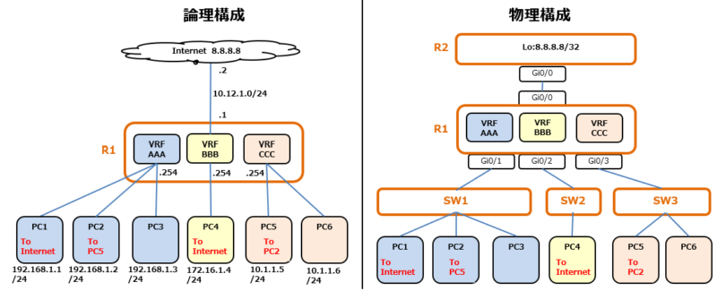
1つのルータにVRFを3つ作成し、配下にPCを配列した構成をCiscoCMLで作成する。
基本はVRF内で通信するポリシーになるが、一部static-routeのroute-leakingにより
通信できるようにする。
構成
通信フロー
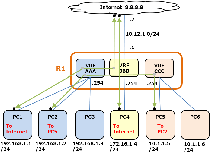
route-leakする通信達
- PC1(VRF AAA) ⇔ 8.8.8.8 (VRF BBB) 間で通信できるようにする
- PC2(VRF AAA) ⇔ PC5 (VRF CCC)
その他はVRF内での通信が完結する事とする。
Config
R1-config click
hostname R1
!
ip vrf AAA
 rd 1:1
!
ip vrf BBB
 rd 2:2
!
ip vrf CCC
 rd 3:3
!
interface GigabitEthernet0/0
 ip vrf forwarding BBB
 ip address 10.12.1.1 255.255.255.0
!
interface GigabitEthernet0/1
 ip vrf forwarding AAA
 ip address 192.168.1.254 255.255.255.0
!
interface GigabitEthernet0/2
 ip vrf forwarding BBB
 ip address 172.16.1.254 255.255.255.0
!
interface GigabitEthernet0/3
 ip vrf forwarding CCC
 ip address 10.1.1.254 255.255.255.0
!
ip route 10.1.1.5 255.255.255.255 GigabitEthernet0/3
ip route 10.12.1.2 255.255.255.255 GigabitEthernet0/0
ip route 192.168.1.1 255.255.255.255 GigabitEthernet0/1
ip route 192.168.1.2 255.255.255.255 GigabitEthernet0/1
ip route vrf AAA 0.0.0.0 0.0.0.0 10.12.1.2 global
ip route vrf AAA 10.1.1.5 255.255.255.255 10.1.1.5 global
ip route vrf BBB 0.0.0.0 0.0.0.0 10.12.1.2
ip route vrf BBB 192.168.1.1 255.255.255.255 192.168.1.1 global
ip route vrf CCC 192.168.1.2 255.255.255.255 192.168.1.2 global
!
control-plane
!
end
R2-config click
hostname R2
!
interface Loopback0
 ip address 8.8.8.8 255.255.255.255
!
interface GigabitEthernet0/0
 ip address 10.12.1.2 255.255.255.0
!
ip route 0.0.0.0 0.0.0.0 10.12.1.1
!
control-plane
!
end
static routeについて
①ip route 10.1.1.5 255.255.255.255 GigabitEthernet0/3
⇒⑥のNext-hopを定義するルート

②ip route 10.12.1.2 255.255.255.255 GigabitEthernet0/0
⇒⑤のNext-hopを定義するルート

③ip route 192.168.1.1 255.255.255.255 GigabitEthernet0/1
⇒⑧のNext-hopを定義するルート

④ip route 192.168.1.2 255.255.255.255 GigabitEthernet0/1
⇒⑨のNext-hopを定義するルート

⑤ip route vrf AAA 0.0.0.0 0.0.0.0 10.12.1.2 global
⇒[VRF AAA]にインターネット向けルートのデフォルトルートをleakする

⑥ip route vrf AAA 10.1.1.5 255.255.255.255 10.1.1.5 global
⇒[VRF AAA]にPC5[VRF CCC]向けルートをleakする

⑦ip route vrf BBB 0.0.0.0 0.0.0.0 10.12.1.2
⇒[VRF BBB]内でのインターネット向けルート

⑧ip route vrf BBB 192.168.1.1 255.255.255.255 192.168.1.1 global
⇒[VRF BBB]にPC1[VRF AAA]向けルートをleakする(インターネットからのダウンリンク)

⑨ip route vrf CCC 192.168.1.2 255.255.255.255 192.168.1.2 global
⇒[VRF CCC]にPC1[VRF AAA]向けルートをleakする
R1ログ
各VRFルーティングテーブル & グローバルルーティングテーブル
赤文字は、route-leakingで必要で設定したルート
R1#show ip route vrf AAA
Routing Table: AAA
Gateway of last resort is 10.12.1.2 to network 0.0.0.0

S*    0.0.0.0/0 [1/0] via 10.12.1.2
      10.0.0.0/32 is subnetted, 1 subnets
S        10.1.1.5 [1/0] via 10.1.1.5
      192.168.1.0/24 is variably subnetted, 2 subnets, 2 masks
C        192.168.1.0/24 is directly connected, GigabitEthernet0/1
L        192.168.1.254/32 is directly connected, GigabitEthernet0/1
R1#show ip route vrf BBB
Routing Table: BBB
Gateway of last resort is 10.12.1.2 to network 0.0.0.0

S*    0.0.0.0/0 [1/0] via 10.12.1.2
      10.0.0.0/8 is variably subnetted, 2 subnets, 2 masks
C        10.12.1.0/24 is directly connected, GigabitEthernet0/0
L        10.12.1.1/32 is directly connected, GigabitEthernet0/0
      172.16.0.0/16 is variably subnetted, 2 subnets, 2 masks
C        172.16.1.0/24 is directly connected, GigabitEthernet0/2
L        172.16.1.254/32 is directly connected, GigabitEthernet0/2
      192.168.1.0/32 is subnetted, 1 subnets
S        192.168.1.1 [1/0] via 192.168.1.1
R1#show ip route vrf CCC
Routing Table: CCC
Gateway of last resort is not set

      10.0.0.0/8 is variably subnetted, 2 subnets, 2 masks
C        10.1.1.0/24 is directly connected, GigabitEthernet0/3
L        10.1.1.254/32 is directly connected, GigabitEthernet0/3
      192.168.1.0/32 is subnetted, 1 subnets
S        192.168.1.2 [1/0] via 192.168.1.2
R1#show ip route
Gateway of last resort is not set

      10.0.0.0/32 is subnetted, 2 subnets
S        10.1.1.5 is directly connected, GigabitEthernet0/3
S        10.12.1.2 is directly connected, GigabitEthernet0/0
      192.168.1.0/32 is subnetted, 2 subnets
S        192.168.1.1 is directly connected, GigabitEthernet0/1
S        192.168.1.2 is directly connected, GigabitEthernet0/1
